Ouput Device
This week assignment is to add a output device to our microcontroller that you have designed and program it do something.
There are many options available to us, some of them are:
LED array
LCD
Speaker
DC motor
Stepper motor, etc
I decided to drive stepper motor using ATtiny 44A. First step is to know about stepper motor, how it works. Some of the key points are mentioned below :
Stepper Motor:

Introduction:
Step motors (often referred as stepper motors) are different from all other types of electrical drives in the sense that they operate on discrete control pulses received and rotate in discrete steps. On the other hand ordinary electrical a.c and d.c drives are analog in nature and rotate continuously depending on magnitude and polarity of the control signal received. The discrete nature of operation of a step motor makes it suitable for directly interfacing with a computer and direct computer control. These motors are widely employed in industrial control, specifically for CNC machines, where open loop control in discrete steps are acceptable. These motors can also be adapted for continuous rotation.
Construction:
Step motors are normally of two types: (a) permanent magnet and (b) variable reluctance type. In a step motor the excitation voltage to the coils is d.c. and the number of phases indicates the number of windings. In both the two cases the excitation windings are in the stator. In a permanent magnet type step motor the rotor is a permanent magnet with a number of poles. On the other hand the rotor of a variable reluctance type motor is of a cylindrical structure with a number of projected teeth

Using Old Stepper Motor
How to use an old six wire stepper motor. This was an old stepper motor that I pulled out my junk pile, I'm not sure what it came from. Below I'll show you how we can figure out how the which wire belong to the same winding.The easiest way to do this is with a simple multimeter.
Step 1: Measure and Record the Resistance for All Six Wires
Most stepper motors come with four, six, or eight wires. This motor uses six wires. What we need to do is measure the resistance from one motor wire to another. This is because of the way stepper motors are made, stepper motors will have two coils and since this motor has six wires that means there are 3 wires per coil. Each of the two coils will have a common wire attached to the center of the coil, we don't want to use this wire. The way that we can determine which wire this is his by measuring resistance, and the resistance from one of the center wires to one of the other wires on the same coil will be smaller than the other pairs. If two wires are not on the same coil, you will measure an open circuit. Here are the resistances is that I measured.

1. If there is reading on the multimeter then wire are part of the same winding (coil).
2.If there is no reading on the multimeter then wire are NOT part of the same winding (coil).
3.For wires that are part of the same winding (coil):The Center tap to coil end resistance is half the coil end-coil end resistance.
Step 2: Check whether motor is Unipolar or Bipolar
Controlling of Stepper Motor.
Driver Circuit
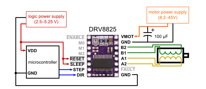
For driving of Stepper motor I will be Using DRV8825 stepper motor driver and ATtiny44a.
First i decided to make a board in which ATtiny44a will be used to pass control signals to DRV8825. Below is the Schematic and Board Layout for my board.Step:- This is input is given as pulses, the frequency of which determines the rotational frequency of the motor, and the number of pulses corresponds to number of steps. So if we need the stepper to move 10 steps, we just give 10 pules, and the rate at which we give the pulse determines how fast the stepper moves those 10 steps.
Dir:- This controls the direction in which the stepper moves. This pin can be High or Low, and obviously high and low corresponds to the CW and CCW rotations.
Then there are more pins which we could use or somehow bypass. Including
MS1, MS2, MS3 :- Micro-stepping selection
Normally low, could be set high as per the table to enable micro-stepping for higher resolution movements.
Enable:- (Normally Low) Setting this Pin High, will disable the FETs in the chip, killing the power to the motor.
Sleep:- (Normally High) Set this pin Low to put the chip in sleep mode to save power when the Motor/Chip is not in use.
Reset:- (Normally Floating) This is a floating pin and should be kept high to use the motor normally, when set low the motor shall return to the original position the motor was in when the chip was turned on. Should refer to the Data-sheet for more information. If this pin is low all STEP signals are ignored.
Schematic and Board
I will be using Eagle 7.7.0 to make schematic for my board. Below is the snapshot for the same.

While making the board i used the mirror image of DRV8825 because it is to be connected at the bottom layer. The other thing which is of concern that connections for 12V is made thick as compared to 5V.

Below are the snapshot for image genrated from eagle.


Milling the Board.
Below are the snapshot of the milled board using SRM 20. I used Fab modules to generated the tool path.
Cut depth=0.1mm
Tool Diameter=0.3mm
No.of offset=4
 >
>
Soldering the stuff
Check List:
Voltage regulator (12V- 5V)
ATtiny 44a
Resonator (20MHz)
Capacitor (1 microF)
Resistor (10k)
2x Resistor (1k)
ISP connector.
LED (optional)
Diode
I used electrolytic capacitor as it is very difficult to find smd 100 micro Farad . DRV8825 is connected to the bottom layer.


Programming
Using Arduino
First step is to check the board

Program to drive the Stepper Motor.
I followed the following tutorial to learn the program fro stepper motor
www.youtube.com/watch?v=d-IKDQ5vqnU
Full Step Mode
// Stepper Motor Program (Full Step Mode)

// defining all the pins

const int stepPin=1;
const int dirPin=0;
const int MS1=4;
const int MS2=3;
const int MS3=2;
const int ENBL=5;
const int LEDpin=7;


void setup() {
  // put your setup code here, to run once:
pinMode(MS2,OUTPUT);
pinMode(MS3,OUTPUT);
pinMode(ENBL,OUTPUT);
pinMode(stepPin,OUTPUT);
pinMode(dirPin,OUTPUT);
pinMode(MS1,OUTPUT);
pinMode(LEDpin,OUTPUT);
digitalWrite(MS1,LOW);
digitalWrite(MS2,LOW);
digitalWrite(MS3,LOW);
digitalWrite(ENBL,LOW);
digitalWrite(LEDpin,HIGH);
}

void loop() {
  // put your main code here, to run repeatedly:
digitalWrite(dirPin,HIGH);     // Set the direction PIN
for(int x=0; x<2000;x++)


{

  digitalWrite(stepPin,HIGH);    // Set the Step PIN
  delayMicroseconds(1000);       // delay of 1000 microseconds

  digitalWrite(stepPin,LOW);     // Reset the Step PIN
  delayMicroseconds(1000);       // delay of 1000 microseconds


  }
}
Next Step is to Burn bootloader into ATtiny44 and upload the program into the microcontroller.

Output
After connecting the motor to the terminals it started working with full step size
Step Size
Then i tested the motor to run at differnt step size according to the table given below. For this i have to change the level for PIN out at MS1, MS2 & MS3

Using Assembly
;stepper.asm
;
; stepper motor

.include "tn44def.inc"

.org 0              ; sets the programs origin
sbi DDRA, 0         ; set bit in Data Direction Register to mark the Direction pin as output
sbi DDRA, 1         ; set bit in Data Direction Register to mark the Step pin as output
sbi DDRA, 7         ; set bit in Data Direction Register to mark the LED pin as output
sbi DDRA, 2         ; set bit in Data Direction Register to mark the MS3 pin as output
sbi DDRA, 3         ; set bit in Data Direction Register to mark the MS2 pin as output
sbi DDRA, 4         ; set bit in Data Direction Register to mark the MS1 pin as output
sbi DDRA, 5         ; set bit in Data Direction Register to mark the ENABLE pin as output


cbi PORTA, 2	    ;LOW signal at PA2
cbi PORTA, 3        ;LOW signal at PA3
cbi PORTA, 4        ;LOW signal at PA4
cbi PORTA, 5        ;LOW signal at PA5
cbi PORTA, 1        ;LOW signal at PA1
cbi PORTA, 0        ;LOW signal at PA0


loop:
sbi PORTA, 0        ;Set the direction PIN
sbi PORTA, 1        ;Set the Step PIN
sbi PORTA, 7        ;Turn on the LED

    ldi  r18, 26
    ldi  r19, 249
L1: dec  r19
    brne L1
    dec  r18
    brne L1

cbi PORTA, 1        ;reset the Step PIN
cbi PORTA, 7        ;Turn on the LED
    ldi  r18, 26
    ldi  r19, 249
L2: dec  r19
    brne L2
    dec  r18
    brne L2


rjmp loop
Steps to upload the Assembly Program.
Step 1: Write the program in text editor and save it as .asm file and rember to include tn44def.inc in your program
Step 2: As gavrasm is installed in my latop in embedded programming week run the following command to make hex file of your code.
Open terminal in the same folder where code is saved and type avra stepper.asm

Step 3: Burn hex file into the board using sudo avrdude -c usbtiny -p attiny44 -U flash:w:stepper.hex:i

Comparison
Program Size
Arduino :630 bytes
Assembly :62 bytes
Problems faced and Learning during the week.
1. Below you can find the snapshot of the schematic diagram designed in the first attempt. The problem in this design which was realized after miling the board was that DRV8825 has to be connected to the bottom layer.But according to the design the orientation of the PINS was not correct.

2. During the Schematic design i forgot to connect current limiting resistor across the LED. During testing it was seed that LED and all the pins of ATtiny44 are floating wrt GND. LED was glowing even the PIN to which it is connected was LOW.
3. When tested the motor with A4988 the driver started heating and motor was not working. Then i relaized the IC was damaged internally. Then i replaced A4988 with DRV8825